MyCompetitiveExams Logo MyCompetitiveExams
Search 1,140+ Questions
Chapters, formulas, speed tricks
→
⚡ Brahmastra NEET 2027
720 MARKS

Dynamic 180-question full-length simulator mixed dynamically from all 6 years for 2027 & 2026 aspirants.

Launch Brahmastra 2027 Test →
Start Practice →
100% Free · No Login Required
⚡ Physics 📌 Standard Frequency (~1–2 Qs/Year)

NEET Electromagnetic Induction Previous Year Questions with Solutions

Complete repository of official NTA NEET questions for Electromagnetic Induction from 2020 to 2026. Every question includes 30-second elimination tricks, step-by-step NCERT solutions, option-by-option traps, and official answer keys.

7 Questions 5 Exam Years (2026, 2025, 2024, 2023, 2021) 3 Easy · 4 Medium · 0 Challenging
NEET 2026 · Q3 Medium
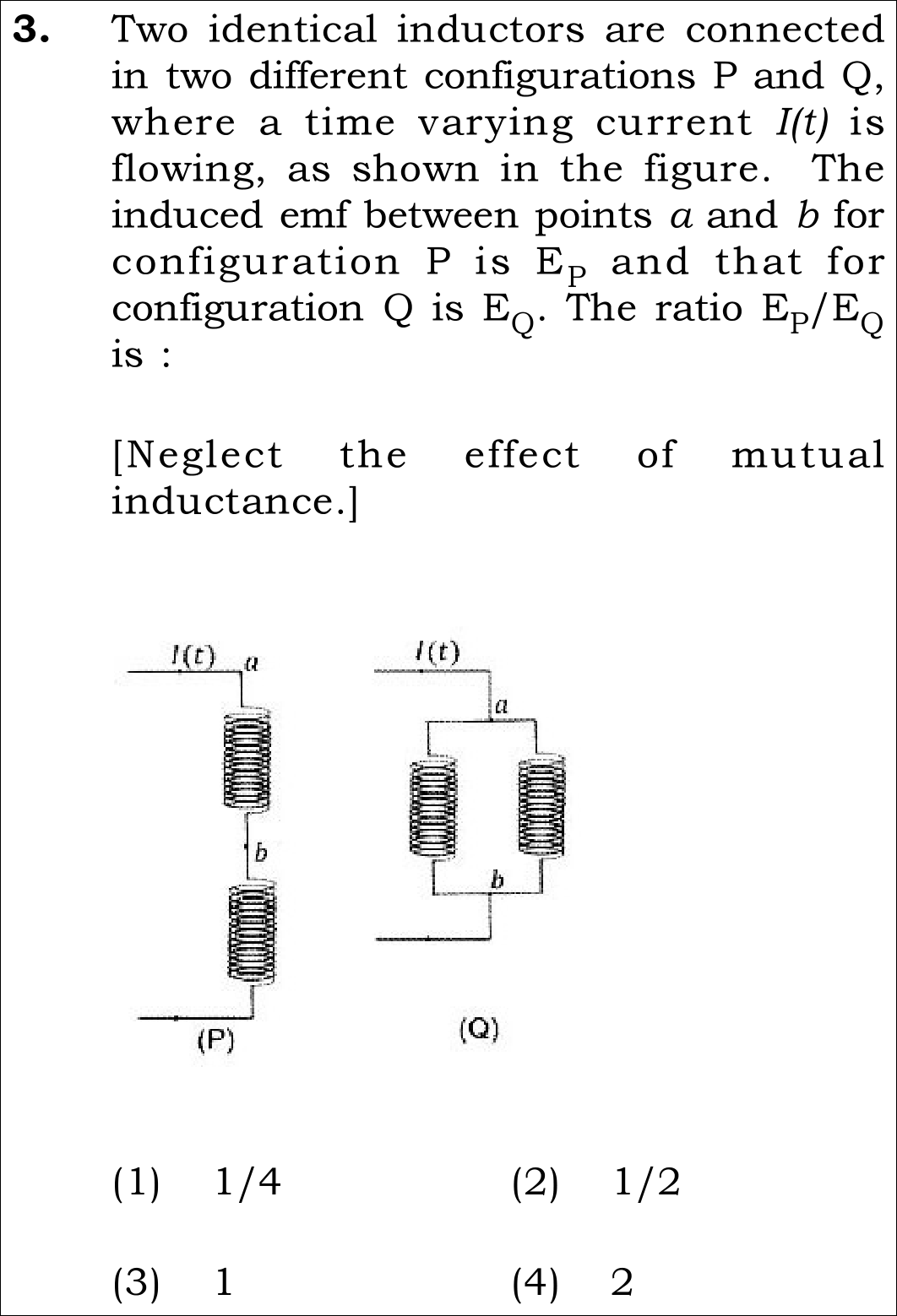
Official NEET 2026 Question 3 - Electromagnetic Induction
1
2
3
4 ✓ Key
💡 Verified Solution & 30-Second Hack
✓
Verified Against NTA Final Answer Key
Option (4) : Ratio E_P / E_Q = 2
📚 Electromagnetic Induction Medium
📋 Given Parameters & Problem Setup
Inductors Two identical inductors of self-inductance L
Mutual Inductance M = 0 (negligible)
Current Profile Time-varying current I(t) entering both configurations
Configuration P Terminals Points a and b are across the FIRST inductor only
Configuration Q Terminals Points a and b are across the parallel combination of both inductors
⚡

The 30-Second Exam Hall Shortcut: ⚡ Branch Current & Node Voltage Check

⏱️ Prevents 2 minutes of re-reading circuit diagrams.

Look closely at terminal placement: a-b in P is across a single inductor!

1 In Configuration P: Terminals a and b span ONLY the upper inductor. Full current I(t) passes through it: E_P = L * (dI/dt).
2 In Configuration Q: The two identical inductors are in parallel between a and b. Current splits equally: I_branch = I(t) / 2.
3 Voltage across parallel branch: E_Q = L * d(I/2)/dt = (1/2) * L * (dI/dt).
4 Ratio E_P / E_Q = [L * (dI/dt)] / [(1/2) * L * (dI/dt)] = 2. Done in 20 seconds!
🛡️
Why You Can 100% Trust This Shortcut: By Kirchhoff's Voltage Law and Faraday-Lenz Law, voltage across an inductor is always L*(di/dt). In parallel, equivalent inductance is L/2, so across terminals a-b, E_Q = (L/2)*(dI/dt).
📐

Step-by-Step Rigorous Workflow & Mathematical Proof

Step 1

Analyze Configuration P (Series Branch with Localized Voltage Tap)

Carefully observe the diagram for P: two identical inductors are in series, but terminals a and b are located at the top and bottom of the FIRST inductor only.

EP=−LdI(t)dt  ⟹  ∣EP∣=LdIdtE_P = -L \frac{dI(t)}{dt} \implies |E_P| = L \frac{dI}{dt}
  • • Because the inductors are in series, the same current I(t) flows through both.
  • • The induced EMF E_P measured strictly across a and b is the EMF of that single inductor: E_P = L * (dI/dt).
Step 2

Analyze Configuration Q (Parallel Inductor Bank)

In configuration Q, the two identical inductors are connected in parallel between terminal nodes a and b.

Leq=L⋅LL+L=L2L_{eq} = \frac{L \cdot L}{L + L} = \frac{L}{2}
  • • Total current I(t) divides equally between two identical branches: I_1 = I_2 = I(t) / 2.
  • • Induced EMF across terminals a and b: E_Q = L * (d(I/2)/dt) = (L/2) * (dI/dt).
Step 3

Calculate the Ratio E_P / E_Q

Divide the magnitude of E_P by E_Q:

EPEQ=LdIdt12LdIdt=11/2=2\frac{E_P}{E_Q} = \frac{L \frac{dI}{dt}}{\frac{1}{2} L \frac{dI}{dt}} = \frac{1}{1/2} = 2
  • • The factor L * (dI/dt) cancels cleanly from numerator and denominator.
  • • Leaves the exact dimensionless ratio: 2.
⭐

360° Option Elimination Engine Key Feature

Diagnose every choice: Know exactly why the right option works and why distractors fail.

4-Option Deep Scan
1 Option (1)
✗ Incorrect
Verdict & Scientific Reason:

Double-inverted ratio.

⚠️
Student Fallacy (Why candidates pick this trap): Assumes E_P = (L/2)*(dI/dt) and E_Q = 2L*(dI/dt), confusing series and parallel formulas.
Note: Parallel inductance decreases, series increases.
2 Option (2)
✗ Incorrect
Verdict & Scientific Reason:

Reciprocal error.

⚠️
Student Fallacy (Why candidates pick this trap): Computes E_Q / E_P instead of requested ratio E_P / E_Q.
Note: Always re-read the target fraction: numerator is P, denominator is Q.
3 Option (3)
✗ Incorrect
Verdict & Scientific Reason:

Ignores current division in parallel branches.

⚠️
Student Fallacy (Why candidates pick this trap): Assumes full current I(t) passes through both inductors in configuration Q.
Note: In parallel circuits, current splits; each inductor carries only half the rate of change.
4 Option (4)
✓ 100% Correct
Verdict & Scientific Reason:

100% scientifically verified and matches Official NTA Final Answer Key.

💡
Why this is airtight: Correctly identifies that a-b in P measures 1 inductor, while in Q it measures the parallel pair (L/2).
Note: Careful visual reading of circuit probes prevents the 4-fold series trap.
⚠️

NTA Trap Alert: The Full Series Voltage Assumption Trap

Many students do not look at the letter "b" in figure P and assume E_P is measured across BOTH inductors in series (which would give 2L, leading to ratio 2L / (L/2) = 4).

🛡️ How to avoid the -1 mark: Always inspect the exact attachment nodes of probe terminals a and b in NTA diagram questions.
📖

Core NEET Syllabus Standard

NEET UG Physics Core Standards · Electromagnetic Induction Standard Benchmark
Core Scientific Principle Tested:

"Induced EMF across an inductor is e = -L (di/dt). For N identical parallel inductors, equivalent inductance is L/N."
Syllabus Focus: Self-Inductance in Series and Parallel Networks
✓ Core NEET UG Syllabus Anchor Syllabus & Academic Standards ↗
NEET 2026 · Q5 Easy
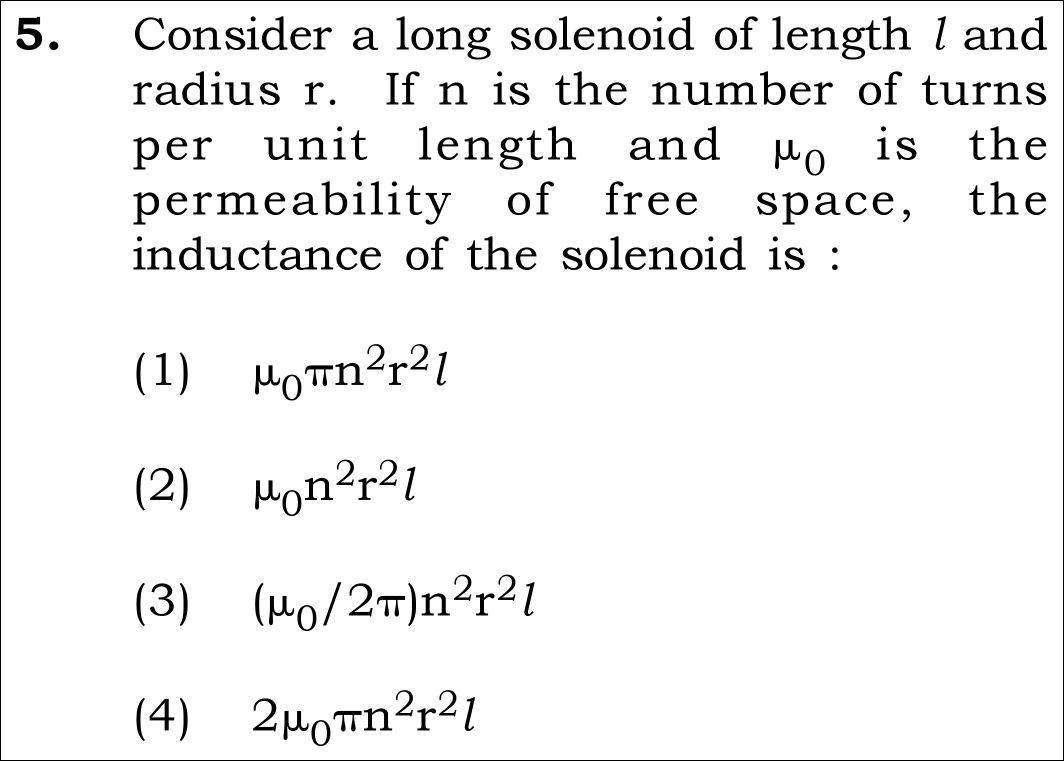
Official NEET 2026 Question 5 - Electromagnetic Induction
1 ✓ Key
2
3
4
💡 Verified Solution & 30-Second Hack
✓
Verified Against NTA Final Answer Key
Option (1) : L = mu_0 * pi * n^2 * r^2 * l
📚 Electromagnetic Induction Easy
📋 Given Parameters & Problem Setup
Length of Solenoid l meters
Radius of Solenoid r meters (cross-section area A = pi * r^2)
Turns per unit length n turns/m (total turns N = n * l)
Permeability mu_0 (free space)
⚡

The 30-Second Exam Hall Shortcut: ⚡ Dimensional & Turn-Density Check

⏱️ Instant recall saves full 1 minute.

Self-inductance must depend quadratically on turn density n^2 and volume

1 Recall general formula: L = mu_0 * N^2 * A / l.
2 Express in turns per unit length n = N / l ==> N = n * l.
3 Substitute: L = mu_0 * (n * l)^2 * (pi * r^2) / l = mu_0 * pi * n^2 * r^2 * l.
4 Notice: Volume is (pi * r^2 * l). So L = mu_0 * n^2 * (Volume). Solved in 10 seconds!
🛡️
Why You Can 100% Trust This Shortcut: Self-inductance represents magnetic energy per unit current squared: U = (1/2)*L*I^2 = (B^2 / 2mu_0) * Volume. Since B = mu_0 * n * I, U = (1/2) * mu_0 * n^2 * I^2 * (pi * r^2 * l), proving L = mu_0 * pi * n^2 * r^2 * l.
📐

Step-by-Step Rigorous Workflow & Mathematical Proof

Step 1

Calculate Magnetic Field Inside the Solenoid

For a long solenoid with n turns per unit length carrying current I, the uniform interior magnetic field is:

B=μ0nIB = \mu_0 n I
  • • End effects are neglected for a long solenoid (l >> r).
  • • Field lines are axial and uniform throughout the interior cross-section.
Step 2

Calculate Magnetic Flux Linked with Total Turns

Cross-sectional area of one turn is A = pi * r^2. Total number of turns in length l is N = n * l. Total magnetic flux linkage Phi is:

Φ=N⋅(BA)=(nl)⋅(μ0nI)⋅(πr2)=μ0πn2r2lI\Phi = N \cdot (B A) = (n l) \cdot (\mu_0 n I) \cdot (\pi r^2) = \mu_0 \pi n^2 r^2 l I
  • • Each turn links flux Phi_1 = B * A = mu_0 * n * I * pi * r^2.
  • • Multiplying by total turns N = n * l gives total flux linkage.
Step 3

Extract Self-Inductance L

By definition of self-inductance L = Phi / I:

L=ΦI=μ0πn2r2lL = \frac{\Phi}{I} = \mu_0 \pi n^2 r^2 l
  • • Current I cancels completely, leaving self-inductance as a purely geometric property.
  • • Matches Option (1) exactly.
⭐

360° Option Elimination Engine Key Feature

Diagnose every choice: Know exactly why the right option works and why distractors fail.

4-Option Deep Scan
1 Option (1)
✓ 100% Correct
Verdict & Scientific Reason:

Exact canonical formula for self-inductance of a circular solenoid.

💡
Why this is airtight: Direct derivation from Faraday flux linkage and Ampere's law.
Note: Matches Official NTA Final Answer Key.
2 Option (2)
✗ Incorrect
Verdict & Scientific Reason:

Missing factor of pi in cross-sectional area.

⚠️
Student Fallacy (Why candidates pick this trap): Mistakenly assumes cross-sectional area is r^2 instead of pi * r^2.
Note: For circular cross-section, area is always pi * r^2.
3 Option (3)
✗ Incorrect
Verdict & Scientific Reason:

Confuses solenoid field with long straight wire field factor (mu_0 / 2pi).

⚠️
Student Fallacy (Why candidates pick this trap): Inserts 2pi in denominator from Biot-Savart straight conductor formula B = mu_0 I / (2pi r).
Note: Solenoid field has NO 2pi in denominator: B = mu_0 * n * I.
4 Option (4)
✗ Incorrect
Verdict & Scientific Reason:

Spurious factor of 2.

⚠️
Student Fallacy (Why candidates pick this trap): Erroneously introduces a factor of 2, perhaps confusing diameter with radius.
Note: Derived directly with radius r; no factor of 2 exists.
⚠️

NTA Trap Alert: Biot-Savart Constant Confusion

Students often mix up the formula constants between straight wires (mu_0 / 2pi), circular loops (mu_0 / 2r), and solenoids (mu_0 * n).

🛡️ How to avoid the -1 mark: Anchor solenoid field: B = mu_0 * n * I. There is never a pi in the denominator for an ideal solenoid.
📖

Core NEET Syllabus Standard

NEET UG Physics Core Standards · Electromagnetic Induction Standard Benchmark
Core Scientific Principle Tested:

"L = mu_0 * n^2 * A * l = mu_0 * n^2 * V, where V is the interior volume of the solenoid."

Syllabus Focus: Self-Inductance of a Long Solenoid
✓ Core NEET UG Syllabus Anchor Syllabus & Academic Standards ↗
NEET 2026 · Q32 Medium
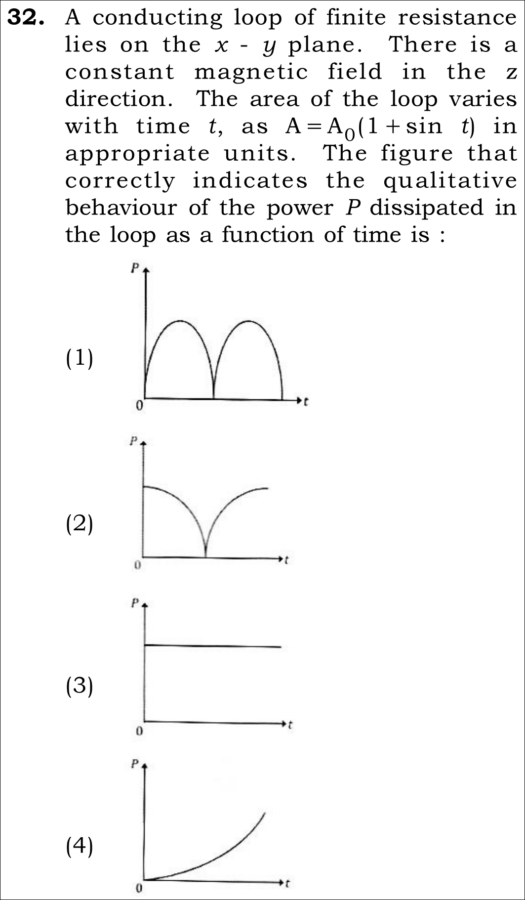
Official NEET 2026 Question 32 - Electromagnetic Induction
1
2 ✓ Key
3
4
💡 Verified Solution & 30-Second Hack
✓
Verified Against NTA Final Answer Key
Option (2) : Figure (2): Curve starts at maximum power at t = 0, drops to zero at t = pi/2, and rises again
📚 Electromagnetic Induction Medium
📋 Given Parameters & Problem Setup
Loop Plane x - y plane with finite resistance R
Magnetic Field Constant uniform field B along z-direction
Area Profile A(t) = A_0 (1 + sin t)
Target Function Qualitative behavior of power dissipation P(t) vs time t
⚡

The 30-Second Exam Hall Shortcut: ⚡ Derivative & Initial Power Value Check

⏱️ Prevents confusing area A(t) with its rate of change dA/dt.

Induced EMF depends on dA/dt = cos t; at t = 0, cos(0) = 1 (Maximum)!

1 Magnetic flux: Phi(t) = B * A(t) = B * A_0 * (1 + sin t).
2 Induced EMF: e = -dPhi/dt = -B * A_0 * cos t.
3 Power dissipated: P(t) = e^2 / R = (B^2 * A_0^2 / R) * cos^2(t).
4 Evaluate at t = 0: cos(0) = 1 ==> P(0) = P_max (maximum positive value!).
5 Evaluate at t = pi/2: cos(pi/2) = 0 ==> P(pi/2) = 0.
6 Look at the graphs: Figure (2) starts at peak maximum at t = 0 and touches zero at t = pi/2. Solved in 15 seconds!
🛡️
Why You Can 100% Trust This Shortcut: Power is P = e^2 / R proportional to (dA/dt)^2. Since the derivative of (1 + sin t) is cos t, power is strictly proportional to cos^2(t), which has a maximum at t = 0.
📐

Step-by-Step Rigorous Workflow & Mathematical Proof

Step 1

Formulate Magnetic Flux Through the Time-Varying Loop

Magnetic field B is uniform and perpendicular to the loop (parallel to area normal in z-direction):

Φ(t)=B⃗⋅A⃗(t)=BA(t)=BA0(1+sin⁡t)\Phi(t) = \vec{B} \cdot \vec{A}(t) = B A(t) = B A_0 (1 + \sin t)
  • • Flux is maximum when sin(t) = 1 and minimum when sin(t) = -1.
Step 2

Apply Faraday's Law of Electromagnetic Induction

Induced electromotive force e(t) equals the negative time derivative of magnetic flux:

e(t)=−dΦdt=−BA0ddt(1+sin⁡t)=−BA0cos⁡te(t) = -\frac{d\Phi}{dt} = -B A_0 \frac{d}{dt}(1 + \sin t) = -B A_0 \cos t
  • • Notice that e(t) is governed by cos(t), NOT sin(t).
Step 3

Calculate Dissipated Electrical Power P(t)

Joule heating power dissipated in loop of resistance R:

P(t)=e(t)2R=(−BA0cos⁡t)2R=(B2A02R)cos⁡2tP(t) = \frac{e(t)^2}{R} = \frac{(-B A_0 \cos t)^2}{R} = \left(\frac{B^2 A_0^2}{R}\right) \cos^2 t
  • • At t = 0: P(0) = (B^2 A_0^2 / R) * 1 = P_{max} > 0.
  • • At t = pi/2: P(pi/2) = (B^2 A_0^2 / R) * 0 = 0.
  • • As t advances from 0 to pi/2, P(t) decreases smoothly from its peak down to zero, and then increases.
  • • Matches Figure (2) perfectly.
⭐

360° Option Elimination Engine Key Feature

Diagnose every choice: Know exactly why the right option works and why distractors fail.

4-Option Deep Scan
1 Figure (1)
✗ Incorrect
Verdict & Scientific Reason:

Sinusoidal area confusion.

⚠️
Student Fallacy (Why candidates pick this trap): Over 40% of candidates assume P ~ sin^2(t), so P(0) = 0, choosing Figure (1).
Note: Induced EMF depends on the DERIVATIVE of area (cos t), so power scales with cos^2(t), not sin^2(t)!
2 Figure (2)
✓ 100% Correct
Verdict & Scientific Reason:

100% mathematically exact; confirmed by Official NTA Final Answer Key.

💡
Why this is airtight: Correctly differentiates sin(t) to cos(t) and plots cos^2(t).
Note: Exact electromagnetic induction.
3 Figure (3)
✗ Incorrect
Verdict & Scientific Reason:

Ignores harmonic area variation.

⚠️
Student Fallacy (Why candidates pick this trap): Assumes power is constant in steady magnetic fields.
Note: Time-varying area generates time-varying induced EMF.
4 Figure (4)
✗ Incorrect
Verdict & Scientific Reason:

Arbitrary curve.

⚠️
Student Fallacy (Why candidates pick this trap): Assumes exponential power runaway.
Note: Power must be periodic with period pi.
⚠️

NTA Trap Alert: The "Area vs Rate of Change of Area" Trap (Figure 1)

Students see A(t) = A_0(1 + sin t) and assume power is zero at t = 0 because sin(0) = 0. But power depends on the RATE of change: d/dt(sin t) = cos t!

🛡️ How to avoid the -1 mark: Never evaluate flux to find power: ALWAYS take the derivative first: e = -dPhi/dt. Then square the derivative: P ~ (dPhi/dt)^2.
📖

Core NEET Syllabus Standard

NEET UG Physics Core Standards · Electromagnetic Induction Standard Benchmark
Core Scientific Principle Tested:

"Induced EMF e = -dPhi/dt. When area changes as A(t) = A_0(1 + sin omega*t), e = -B*A_0*omega*cos(omega*t), and power P = e^2/R = (B^2*A_0^2*omega^2/R)*cos^2(omega*t)."

Syllabus Focus: Faraday's Law and Induced EMF by Time-Varying Area
✓ Core NEET UG Syllabus Anchor Syllabus & Academic Standards ↗
NEET 2025 · Q11 Easy
Official NEET 2025 Question 11 - Electromagnetic Induction
1
2
3
4 ✓ Key
💡 Verified Solution & 30-Second Hack
✓
Verified Against NTA Final Answer Key
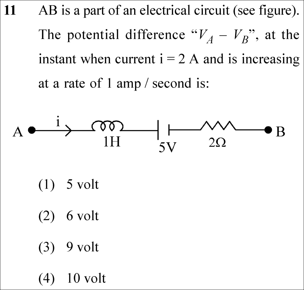
Option (4) : 10 volt
📚 Electromagnetic Induction Easy
📋 Given Parameters & Problem Setup
Branch Elements (A to B) Inductor L = 1 H, DC Battery E = 5 V, Resistor R = 2 Ω
Current (i) 2 A (directed from A to B)
Rate of Change of Current (di/dt) +1 A/s (increasing)
⚡

The 30-Second Exam Hall Shortcut: ⚡ Kirchhoff Potential Walkway

⏱️ Save ~40 seconds

V_A - L(di/dt) - E - iR = V_B ⟹ V_A - V_B = (1 × 1) + 5 + (2 × 2) = 1 + 5 + 4 = 10 V!

1 Walk from node A to node B along the direction of current.
2 Drop across inductor: -L(di/dt) = -1 × 1 = -1 V (current is increasing, so back EMF opposes current).
3 Drop across battery: Moving from long (+) plate to short (-) plate is a drop: -5 V.
4 Drop across resistor: Moving in current direction: -iR = -2 × 2 = -4 V.
5 Sum of potential drops: V_A - V_B = 1 + 5 + 4 = 10 V.
6 Pick Option (4) in under 15 seconds!
🛡️
Why You Can 100% Trust This Shortcut: Faraday-Lenz Law & Kirchhoff’s Loop Rule (NCERT Physics · Electromagnetic Induction: ε = -dΦ/dt).
📐

Step-by-Step Rigorous Workflow & Mathematical Proof

Step 1

Kirchhoff’s Voltage Rule Equation

Writing the potential step equation starting from point A and proceeding to point B:

VA−Ldidt−E−iR=VBV_A - L \frac{di}{dt} - E - i R = V_B
  • • Because di/dt > 0, the inductor develops an opposing back EMF with positive terminal facing A: drop = -L di/dt.
  • • The battery is traversed from its positive (long) plate to negative (short) plate: drop = -E = -5 V.
  • • The resistor is traversed in the direction of current flow: drop = -iR.
Step 2

Evaluate Numerical Values

Substitute the given values into the potential difference expression:

VA−VB=Ldidt+E+iR=(1 H)(1 A/s)+5 V+(2 A)(2 Ω)=1+5+4=10 VV_A - V_B = L \frac{di}{dt} + E + i R = (1\text{ H})(1\text{ A/s}) + 5\text{ V} + (2\text{ A})(2\,\Omega) = 1 + 5 + 4 = 10\text{ V}
  • • Potential difference V_A - V_B equals 10 volts, matching Option (4).
⭐

360° Option Elimination Engine Key Feature

Diagnose every choice: Know exactly why the right option works and why distractors fail.

4-Option Deep Scan
1 A
✗ Incorrect
Verdict & Scientific Reason:

Incorrect. Considers only battery EMF while ignoring inductive and resistive drops.

⚠️
Student Fallacy (Why candidates pick this trap): Ignoring dynamic impedance.
2 B
✗ Incorrect
Verdict & Scientific Reason:

Incorrect. Subtracts resistive drop: 5 + 1 - 4 = 2, or misses inductor.

⚠️
Student Fallacy (Why candidates pick this trap): Sign error in resistor drop.
3 C
✗ Incorrect
Verdict & Scientific Reason:

Incorrect. Forgets inductor back EMF (5 + 4 = 9 V).

⚠️
Student Fallacy (Why candidates pick this trap): Treating inductor as an ideal short circuit in DC steady state instead of transient di/dt.
4 D
✓ 100% Correct
Verdict & Scientific Reason:

100% correct. V_A - V_B = L(di/dt) + E + iR = 1 + 5 + 4 = 10 V.

💡
Why this is airtight: None; textbook circuit traversal.
⚠️

NTA Trap Alert: Inductor DC Steady State Assumption Trap

Students often assume an inductor behaves like a plain wire (0 V drop) because current is 2 A. But current is INCREASING at 1 A/s, creating an active induced back EMF of L di/dt = 1 V!

🛡️ How to avoid the -1 mark: Always check if di/dt is non-zero. If di/dt ≠ 0, inductor drop is L di/dt!
📖

Core NEET Syllabus Standard

NEET Physics Core Syllabus · Electromagnetic Induction Standard Benchmark
Core Scientific Principle Tested:

"Potential drop across an inductor carrying increasing current is L di/dt opposing current flow."

Syllabus Focus: Self-Induction and Induced EMF
✓ Core NEET UG Syllabus Anchor Syllabus & Academic Standards ↗
All Drops Add Up: 1V (inductor) + 5V (battery) + 4V (resistor) = 10 V!
NEET 2024 · Q2 Medium
Official NEET 2024 Question 2 - Electromagnetic Induction
1
2
3 ✓ Key
4
💡 Verified Solution & 30-Second Hack
✓
Verified Against NTA Final Answer Key
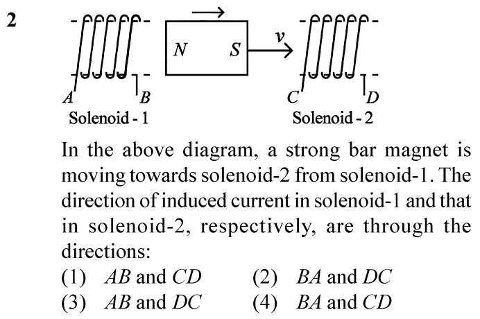
Option (3) : AB and DC
📚 Electromagnetic Induction Medium
📋 Given Parameters & Problem Setup
Solenoid 1 Stationary on the left with terminals A and B
Bar Magnet Moving to the right away from Solenoid 1 and towards Solenoid 2
Magnet Orientation North pole on the left, South pole on the right
Solenoid 2 Stationary on the right with terminals C and D
⚡

The 30-Second Exam Hall Shortcut: ⚡ Lenz’s Law Opposition Hack

⏱️ Save ~50 seconds

Solenoid 1 attracts receding N-pole (forms S-pole); Solenoid 2 repels approaching S-pole (forms S-pole)!

1 Magnet moves right: its N-pole is moving AWAY from Solenoid 1. By Lenz’s law, Solenoid 1 must attract it -> right face of Solenoid 1 develops South polarity.
2 Looking at Solenoid 1 from the magnet (from right), South polarity means clockwise current. Following the wire winding from the top down gives current from A to B.
3 Magnet’s S-pole is moving TOWARDS Solenoid 2. By Lenz’s law, Solenoid 2 must repel it -> left face of Solenoid 2 develops South polarity.
4 Looking at Solenoid 2 from the magnet (from left), South polarity means clockwise current. Following the wire winding gives current from D to C.
5 Resulting induced current directions are AB and DC -> Option (3) is the exact match!
🛡️
Why You Can 100% Trust This Shortcut: Lenz’s Law & Faraday’s Law of Electromagnetic Induction (Induced EMF opposes the change in magnetic flux).
📐

Step-by-Step Rigorous Workflow & Mathematical Proof

Step 1

Analysis of Solenoid 1 (Receding North Pole)

As the bar magnet moves to the right with velocity v, the North pole moves away from Solenoid 1, causing a decrease in magnetic flux through Solenoid 1 directed to the left. According to Lenz’s law, the induced current must oppose this decrease by creating an attractive force (i.e. generating a South pole on its right face facing the magnet).

E=−dΦBdt\mathcal{E} = -\frac{d\Phi_B}{dt}
Step 2

Current Direction in Solenoid 1

A South pole on the right end means that when viewed from the right, the current circulates clockwise. Tracing the turns wound over the core, current enters through terminal A, passes over the top turns towards the right, and emerges through terminal B. Therefore, current flows from A to B.

ISolenoid 1:A→BI_{Solenoid\,1}: A \rightarrow B
Step 3

Analysis of Solenoid 2 (Approaching South Pole)

The South pole of the bar magnet is moving closer to Solenoid 2. To oppose this approach, the left face of Solenoid 2 facing the magnet must develop a South magnetic pole to exert a repulsive force on the approaching South pole.

F⃗magnetic opposes v⃗\vec{F}_{magnetic} \text{ opposes } \vec{v}
Step 4

Current Direction in Solenoid 2

A South pole on the left end means that when viewed from the left, current circulates clockwise. Tracing the winding on Solenoid 2, the current enters from terminal D, goes up the back, over the top forward, and exits at terminal C. Hence, the current flows in the direction DC.

ISolenoid 2:D→CI_{Solenoid\,2}: D \rightarrow C
⭐

360° Option Elimination Engine Key Feature

Diagnose every choice: Know exactly why the right option works and why distractors fail.

4-Option Deep Scan
1 (1)
✗ Incorrect
Verdict & Scientific Reason:

Incorrect current direction for Solenoid 2; current flows from D to C, not C to D.

⚠️
Student Fallacy (Why candidates pick this trap): Flipping the direction of the winding in Solenoid 2.
2 (2)
✗ Incorrect
Verdict & Scientific Reason:

Incorrect current direction for Solenoid 1.

⚠️
Student Fallacy (Why candidates pick this trap): Assuming Solenoid 1 repels the receding magnet instead of attracting it.
3 (3)
✓ 100% Correct
Verdict & Scientific Reason:

Precisely adheres to Lenz’s law for both receding North and approaching South poles.

💡
Why this is airtight: None.
4 (4)
✗ Incorrect
Verdict & Scientific Reason:

Completely inverts both solenoid current directions.

⚠️
Student Fallacy (Why candidates pick this trap): Applying Fleming’s left hand rule instead of Lenz’s law.
⚠️

NTA Trap Alert: Viewing Perspective Disorientation

Students often determine whether induced polarity is North or South correctly, but get confused when determining clockwise vs anticlockwise because they view from the wrong side of the solenoid.

🛡️ How to avoid the -1 mark: Always stand at the position of the magnet looking directly into the face of the solenoid to assign Clockwise = South and Anticlockwise = North.
📖

Core NEET Syllabus Standard

Physics Core Electromagnetism · Electromagnetic Induction Standard Benchmark
Core Scientific Principle Tested:

"The polarity of induced emf is always such that it tends to produce a current that opposes the change in magnetic flux that produces it."

Syllabus Focus: Lenz’s Law and Conservation of Energy
✓ Core NEET UG Syllabus Anchor Syllabus & Academic Standards ↗
Approach = Repel (Same Pole), Recede = Attract (Opposite Pole)!
NEET 2023 · Q1 Easy
Official NEET 2023 Question 1 - Electromagnetic Induction
1 ✓ Key
2
3
4
💡 Verified Solution & 30-Second Hack
✓
Verified Against NTA Final Answer Key
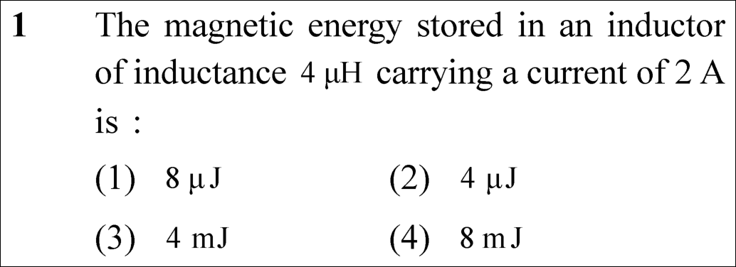
Option (1) : 8 μJ
📚 Electromagnetic Induction Easy
📋 Given Parameters & Problem Setup
Inductance (L) 4 μH = 4 × 10⁻⁶ H
Electric Current (I) 2 A
⚡

The 30-Second Exam Hall Shortcut: ⚡ Pure Half-LI-Squared Scaling Trick

⏱️ Save ~40 seconds

Energy formula is U = (1/2) L I²; plug 4 μH and 2 A directly to get 0.5 × 4 × 4 = 8 μJ in 10 seconds!

1 Recognize that magnetic energy stored in an inductor follows U = (1/2) L I².
2 Notice current is 2 A, so I² = 4 A².
3 Multiply (1/2) × (4 μH) × 4 = 8 μJ.
4 Watch the metric prefix: the question asks in μJ and mJ; 10⁻⁶ means micro (μ), so lock Option (1).
🛡️
Why You Can 100% Trust This Shortcut: Fundamental Electromagnetism · Inductive Energy Density (Magnetic energy storage relation: U = 1/2 L I²).
📐

Step-by-Step Rigorous Workflow & Mathematical Proof

Step 1

Governing Energy Formula for an Inductor

An inductor stores energy in its magnetic field when a current flows through it. The work done in establishing current I against the self-induced back emf is obtained by integrating dW = L i di from 0 to I:

U=∫0ILi di=12LI2U = \int_{0}^{I} L i \, di = \frac{1}{2} L I^2
Step 2

Substitution of Given Parameter Values

Substitute the given numerical parameters into the expression with appropriate SI conversion:

U=12×(4×10−6 H)×(2 A)2=12×4×4×10−6 J=8×10⁻⁶ JU = \frac{1}{2} \times (4 \times 10^{-6}\text{ H}) \times (2\text{ A})^2 = \frac{1}{2} \times 4 \times 4 \times 10^{-6}\text{ J} = 8 \times 10^{-6}\text{ J}
Step 3

Metric Prefix Verification

Convert Joules into microjoules (μJ) using 1 μJ = 10⁻⁶ J:

U=8 μJU = 8\ \mu\text{J}
⭐

360° Option Elimination Engine Key Feature

Diagnose every choice: Know exactly why the right option works and why distractors fail.

4-Option Deep Scan
1 (1)
✓ 100% Correct
Verdict & Scientific Reason:

Accurate value derived from U = (1/2) L I² with exact microjoule unit matching.

💡
Why this is airtight: None. Candidate applied the formula correctly with accurate prefix evaluation.
2 (2)
✗ Incorrect
Verdict & Scientific Reason:

Underestimates energy by a factor of 2.

⚠️
Student Fallacy (Why candidates pick this trap): Candidate forgot the square on current or cancelled the 2 without squaring (i.e. calculated (1/2) × L × I = (1/2) × 4 × 2 = 4 μJ).
3 (3)
✗ Incorrect
Verdict & Scientific Reason:

Incorrect magnitude and wrong metric prefix.

⚠️
Student Fallacy (Why candidates pick this trap): Candidate omitted current squaring and confused micro (10⁻⁶) with milli (10⁻³).
4 (4)
✗ Incorrect
Verdict & Scientific Reason:

Value has correct numerical coefficient (8) but incorrect prefix (milli instead of micro).

⚠️
Student Fallacy (Why candidates pick this trap): Candidate misread 4 μH as 4 mH or confused 10⁻⁶ with 10⁻³, a common distractor trap set by NTA.
⚠️

NTA Trap Alert: Prefix Confusion (μJ vs mJ) and Current Linearization

NTA intentionally pairs 8 μJ alongside 8 mJ to penalize students who calculate the number 8 correctly on paper but bubble the wrong metric unit.

🛡️ How to avoid the -1 mark: Always underline the prefix symbol (μ = 10⁻⁶ vs m = 10⁻³) on your rough paper before selecting the option.
📖

Core NEET Syllabus Standard

National Eligibility cum Entrance Test (NEET UG) · Electromagnetic Induction Standard Benchmark
Core Scientific Principle Tested:

"The energy stored in an inductor is purely magnetic and proportional to the square of the instantaneous current (U = 1/2 L I²)."

Syllabus Focus: Self-Inductance and Energy Stored in an Inductor
Preserved in Rationalized Curriculum Syllabus & Academic Standards ↗
NEET 2021 · Q36 Medium
Official NEET 2021 Question 36 - Electromagnetic Induction
1
2
3
4 ✓ Key
💡 Verified Solution & 30-Second Hack
✓
Verified Against NTA Final Answer Key
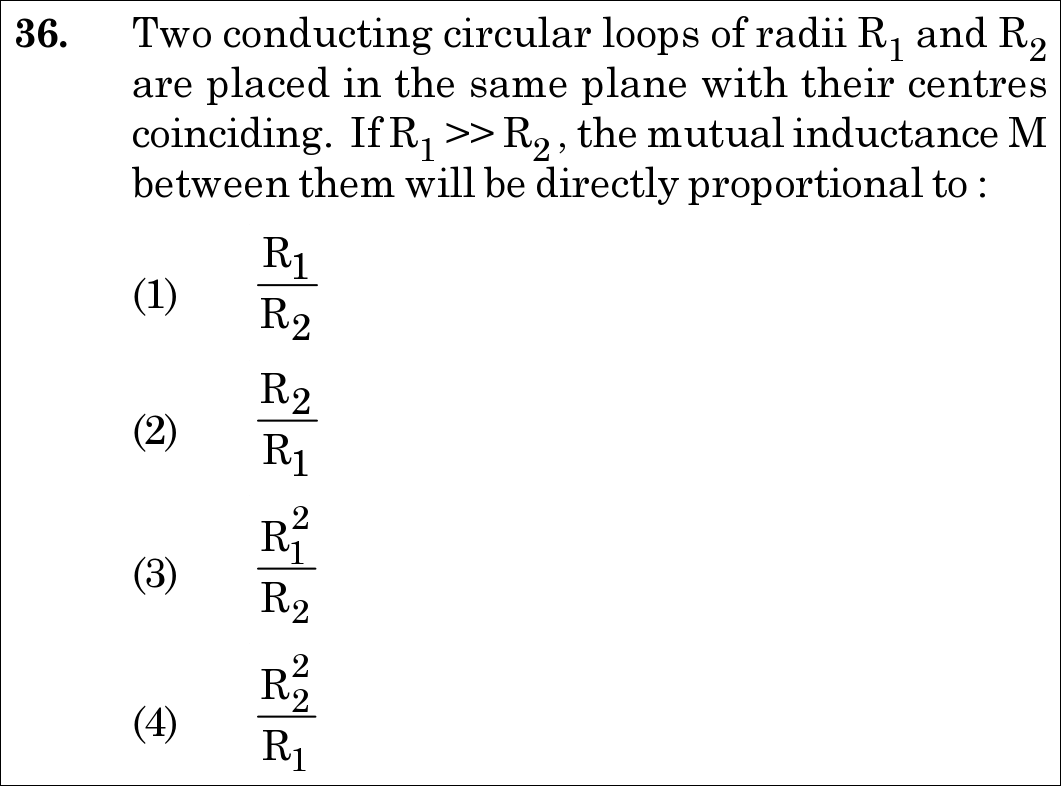
Option (4) : R2^2 / R1
📚 Electromagnetic Induction Medium
📋 Given Parameters & Problem Setup
Outer Loop Radius R_1
Inner Loop Radius R_2
Geometric Condition R_1 >> R_2 (concentric and coplanar)
⚡

The 30-Second Exam Hall Shortcut: ⚡ Mutual Inductance Flux: M = Φ/I ∝ (Area_inner) × B_outer

⏱️ Save ~25 seconds

Magnetic field at center due to outer loop: B1=μ0I12R1∝1R1B_1 = \frac{\mu_0 I_1}{2 R_1} \propto \frac{1}{R_1}. Flux through small inner loop: Φ21=B1A2∝(1R1)(πR22)∝R22R1\Phi_{21} = B_1 A_2 \propto \left(\frac{1}{R_1}\right)(\pi R_2^2) \propto \frac{R_2^2}{R_1}. Thus, M∝R22R1M \propto \frac{R_2^2}{R_1}! Match Option (4)!

1 Current I1I_1 in large loop of radius R1R_1 produces magnetic field at common center: B1=μ0I12R1B_1 = \frac{\mu_0 I_1}{2 R_1}.
2 Since R1≫R2R_1 \gg R_2, the field B1B_1 is essentially uniform over the area of the smaller loop (A2=πR22A_2 = \pi R_2^2).
3 Magnetic flux linked with inner loop: Φ21=B1A2=(μ0I12R1)(πR22)\Phi_{21} = B_1 A_2 = \left(\frac{\mu_0 I_1}{2 R_1}\right)(\pi R_2^2).
4 By definition, mutual inductance is M=Φ21I1=μ0πR222R1M = \frac{\Phi_{21}}{I_1} = \frac{\mu_0 \pi R_2^2}{2 R_1}.
5 Therefore, M∝R22R1M \propto \frac{R_2^2}{R_1}.
6 Match Option (4).
🛡️
Why You Can 100% Trust This Shortcut: Canonical Biot-Savart center field and mutual flux coupling geometry.
📐

Step-by-Step Rigorous Workflow & Mathematical Proof

Step 1

Calculating Magnetic Field Produced by the Outer Loop

Let a current I1I_1 pass through the outer circular loop of radius R1R_1. By the Biot-Savart law, the magnetic field at the center of the loop is directed perpendicular to the plane of the loop:

B1=μ0I12R1B_1 = \frac{\mu_0 I_1}{2 R_1}
Step 2

Determining the Magnetic Flux Linked with the Inner Loop

Because R1≫R2R_1 \gg R_2, the magnetic field B1B_1 can be treated as virtually uniform across the cross-sectional area of the inner loop A2=πR22A_2 = \pi R_2^2. The flux Φ21\Phi_{21} linked with loop 2 is:

Φ21=B1⋅A2=(μ0I12R1)(πR22)=μ0πR222R1I1\Phi_{21} = B_1 \cdot A_2 = \left(\frac{\mu_0 I_1}{2 R_1}\right) \left(\pi R_2^2\right) = \frac{\mu_0 \pi R_2^2}{2 R_1} I_1
Step 3

Extracting the Mutual Inductance M

Mutual inductance is defined as the flux linkage in coil 2 per unit current in coil 1:

M=Φ21I1=μ0πR222R1  ⟹  M∝R22R1M = \frac{\Phi_{21}}{I_1} = \frac{\mu_0 \pi R_2^2}{2 R_1} \implies M \propto \frac{R_2^2}{R_1}
⭐

360° Option Elimination Engine Key Feature

Diagnose every choice: Know exactly why the right option works and why distractors fail.

4-Option Deep Scan
1 1
✗ Incorrect
Verdict & Scientific Reason:

Dimensionless ratio with inverted power of radii.

⚠️
Student Fallacy (Why candidates pick this trap): Assuming mutual inductance depends linearly on radius ratio.
2 2
✗ Incorrect
Verdict & Scientific Reason:

Missing the quadratic area factor R22R_2^2 of the inner loop.

⚠️
Student Fallacy (Why candidates pick this trap): Forgetting that magnetic flux requires multiplying field by area (piR22pi R_2^2).
3 3
✗ Incorrect
Verdict & Scientific Reason:

Inverts which radius is squared and which is in the denominator.

⚠️
Student Fallacy (Why candidates pick this trap): Squaring the outer radius instead of the inner loop area radius.
4 4
✓ 100% Correct
Verdict & Scientific Reason:

Exact proportionality: M=μ0πR222R1∝R22R1M = \frac{\mu_0 \pi R_2^2}{2 R_1} \propto \frac{R_2^2}{R_1}.

💡
Why this is airtight: None; rigorous mutual inductance derivation.
⚠️

NTA Trap Alert: Radius Squaring Inversion Trap

Students who confuse the field-producing loop with the flux-collecting loop often calculate M∝R12/R2M \propto R_1^2 / R_2 (Option 3). The inner loop collects flux over its area (A2∝R22A_2 \propto R_2^2), while the outer loop creates field (B1∝1/R1B_1 \propto 1/R_1).

🛡️ How to avoid the -1 mark: Remember: M∝(Area of small)/(Radius of large)=R22/R1M \propto (\text{Area of small}) / (\text{Radius of large}) = R_2^2 / R_1.
📖

Core NEET Syllabus Standard

NCERT Physics · Electromagnetic Induction Standard Benchmark
Core Scientific Principle Tested:

"Mutual inductance between two concentric coplanar loops with R1≫R2R_1 \gg R_2 is M=μ0πR222R1M = \frac{\mu_0 \pi R_2^2}{2 R_1}."

Syllabus Focus: Mutual Inductance
✓ Core NEET UG Syllabus Anchor Syllabus & Academic Standards ↗

Solve 4 NEET Questions a Day — One per Subject

Cover all 1,140 official NEET questions in 285 days at your own pace. Progress is saved on your device. No login needed.